User Guide
This section is a guide to configuring the Scorpion 2DScanner.
The scanner has the following properties:
Multiple area scan cameras can be connected
Each connected camera has these features
resampler, optional, clipping, resampling or both
filter, optional, shading correction or custom filter
image FIFO buffer, optional
The camera images are stitched together
Each camera can be shading corrected
Each camera can be 2D or 3D calibrated
A 3D calibrated 2DScanner is a 3D scanning device
The stitching with 3D calibration is superior to 2D
When stitching multiple cameras, 3D calibration is essential
The 2DScanner acquires and resamples each camera in a separate thread. Moving the resampling into the 2DScanner improves performance, ease of use and abstraction.
It may also increase the latency and slightly decrease the frame rate
Note
The 2DScanner is cross platform and runs on both Scorpion (Windows) and
SMARTedge (Linux ARM64). The same 2DScanner.ini can be shared between
the two: Windows driver, filter and resampler .dll names are mapped
automatically to their Linux .so equivalents at load time
(for example HVGrab_1_0_4_53.dll is loaded as libhvgrab.so).
Image flow
The image flow from cameras to the final scanner image consists of several steps
acquisition - fetching the image from the camera
resampling - clipping the image and/or resampling it to a calibrated image
filter - filtering the resampled image from the camera
stitching - inserting the partial image into the final scanner image matrix - row/column
Resampling
The incoming image may be clipped and/or resampled using an external calibration file. The calibration file is typically created by a Scorpion calibration profile. Resampling is performed in SVLResample.dll.
The resampler option is the name of the calibration file, given as an absolute path or relative to 2DScanner.ini.
Note
Pixel mode (no calibration file) is used when CalibFile is left empty or set to pixels.
From version 1.1.0.31 pixel mode is simplified:
the output size is taken directly from the camera image
no resampler plugin (SVLResample) is required
the
SizeandTopLeftsettings are ignored
Calibrated mode is unchanged.
Filtering
The 2D Scanner camera driver supports optional per-camera image filters configured in the system INI file. A filter is created once when the camera is opened and applied to every acquired frame before the image is passed to the scanner pipeline.
Each camera section and each calibration sub-section can have its own independent filter configuration. Image filters work in both calibrated mode and pixel mode.
Stitching
Each subimage is placed in a matrix - the column is determined by the camera index and the row by the number of stripes (scans) in the final scanner image. If a timeout is used and the time expires, the missing columns are filled with a static pixel value.
Note
Cameras of different width and height can be combined. The images are placed side by side and padded to the height of the tallest, with any empty areas filled black.
Cameras with different pixel depth cannot be combined: the scanner refuses to open and logs a clear error rather than producing a corrupted image.
Installation
The 2DScanner SCD - Scorpion Camera Driver is a virtual camera driver
Installed by the Scorpion Vision Installer.
Use like any other camera driver
Has no GUI
Is configured directly using the 2DScanner.ini file
Multiple 2DScanners can be installed in a profile.
The Scorpion Camera drivers used is specified in the configuration file.
Configuration file
The configuration file 2DScanner.ini is located in the Scorpion profile’s Hardware folder. If missing, create the file manually by using a appropriate example from this documentation.
The inifile has multiple sections
Config - common section
Scanner<nnnn> - individual scanner 1..n configuration
Scanner<nnnn>.Camera<n> - individual scanner n’s camera configuration
Note
There are samples of the configuration file at the end of this guide
Config Section
Common setup for all scanners in the config file
Key |
Default |
Description |
|---|---|---|
CameraDriver |
<driver.dll> |
name of Scorpion Camera Driver for actual cameras attached - SCD |
FilterDLL |
SVLImageFilter.dll |
name of Scorpion Standard filter dll |
ResampleDLL |
SVLResample.dll |
name of Scorpion Standard Resampling dll |
ResampleMode |
0 |
|
Verbose |
0 |
|
Note
CameraDriver must be the same for all cameras connected to a 2DScanner
Example: HVGrab_1_0_4_46.dll - it is required that the SCD SDK is installed
Note
ResampleMode is default bilinear=0 which provides the best resampling - other modes may improve scanning rate
bilinear is the most accurate resampler
nearest neighbour is the fastest
The ResampleDLL - SVLResample.dll is distributed in Scorpion - not adviced to change.
Scanner<nnnn> section
Common setup for all cameras for a single scanner, Scanner<nnnn>. Values in the common section are used for this scanner’s camera values if omitted in the individual camera section.
Key |
Default |
Description |
|---|---|---|
Cameras |
1 |
Number of ‘horizontal’ camera images in the stitched image |
Scans |
1 |
Number of ‘vertical’ scans in the stitched image |
ActiveGrabTimeout |
0 |
Timeout period in milliseconds between triggers or images |
ImageDelay |
0 |
Delay in milliseconds before the completed scan is delivered to the application |
MinScans |
0 |
Minimum scan count to accept the image when a timeout occurs |
Overlap |
0 |
Number of overlap scans copied to the next image |
Scale_x |
1.0 |
‘vertical’ scale of each camera image, defaults to 1 (not yet implemented) |
Scale_y |
1.0 |
‘horizontal’ scale of each camera image, defaults to 1 (not yet implemented) |
TopLeft_x |
0 |
Top left corner x offset in object coordinates relative to calibration (0,0) when a calibration file is used, else offset in pixels. Ignored in pixel mode. |
TopLeft_y |
0 |
Top left corner y offset in object coordinates relative to calibration (0,0) when a calibration file is used, else offset in pixels. Ignored in pixel mode. |
Size_x |
100 |
Resampled height of the final image in object coordinates. Ignored in pixel mode, where the camera image height is used. |
Size_y |
100 |
Resampled width of the final image in object coordinates. Ignored in pixel mode, where the camera image width is used. |
Angle |
0 |
ROI angle in degrees |
Pitch_x |
1.0 |
Pixel size x (height) in the outgoing image |
Pitch_y |
1.0 |
Pixel size y (width) in the outgoing image |
PassThru |
<empty> |
Index of raw images to pass through to Scorpion while scanning. Empty or ‘-’ disables passthru. should be empty in runtime systems |
Active |
0 |
Defines whether a raw (PassThru) image is passed before or after the stitched image when the scan is complete. If Active, the stitched image is passed to the application before the raw image, else after. NOTE! applies to images in the PassThru list only. |
DiscardLostPacket |
0 |
Discard the scan if a lost packet is detected (see scan validation note) |
DiscardSeqError |
0 |
Discard the scan if a FrameNumber sequence error is detected |
DiscardSyncError |
0 |
Discard the scan if a FrameNumber sync error between cameras is detected |
Threaded |
1 |
Threaded resampling. May be turned off for small images/short resampling time. |
RingSize |
32 |
Per-camera capture buffer depth. The larger default absorbs short bursts so no frame is lost at high frame rates. Grown automatically to at least Fifo+1. |
WorkerRtPriority |
8 |
Runs the capture worker thread at real-time priority for smooth, jitter-free scanning. Set 0 to use normal scheduling. See note below. |
Note
When multiple cameras, ie. stitching each ‘stripe’ horizontally, the TopLeft_y for next camera is by default TopLeft_y+Size_y of previous camera, assuming each camera is calibrated to same origin (0,0).
Each parameter Scale / TopLeft / Size / Pitch / Threaded may be overriden for each camera by inserting the keys into the corresponding Scanner<nnnn>.Camera<n> section, see later examples.
When using camera specific calibration file for each camera, TopLeft should be set in each camera section.
Note
Overlap used to created overlapped images
Useful when individual objects are scanned on a conveyor.
The overlap defines the partial scan images or scans to be copied to the next images.
Note
PassThru a python inspired comma separated list of indexes
“0” passes all.
‘’ or ‘-’ to disables passthru.
“1,-1” equals first and last image in scan is passed to scorpion.
disable when running fast rumors of a memory leak
Negative values are from end of the list
should be empty and disabled in runtime systems
Note
MinScan applies when ActiveGrabTimeOut > 0
If MinScans>0
MinScans is number of scans allowed missed.
If no of scans is less than MinScan on timeout, current partial scan is discarded.
If MinScans=0
All timeout scan are silently discarded
Useful when two images are required to be in sync - eg Stereo Vision
Note
Scan validation - DiscardLostPacket, DiscardSeqError and DiscardSyncError cause a scan to be discarded when a transport or synchronisation problem is detected:
DiscardLostPacket - a camera reports a lost packet (GigE transport layer)
DiscardSeqError - a camera’s FrameNumber sequence has a gap
DiscardSyncError - the cameras’ FrameNumbers are not in sync with each other
Use these to drop scans that would otherwise contain torn or mismatched images.
Note
High frame rate scanning - RingSize and WorkerRtPriority keep the cameras running at full rate without falling behind (from version 1.1.0.32):
RingSize is the per-camera capture buffer depth. The default of 32 absorbs short bursts (about 0.6 s at 50 fps) so no frame is lost while a completed scan is handed to the application. It is grown automatically to at least Fifo*+1, and may be overridden per camera in the *Scanner<nnnn>.Camera<n> section.
WorkerRtPriority runs the capture worker thread at real-time priority for smooth, jitter-free scanning. Set 0 to use normal scheduling.
Note
On Linux/SMARTedge real-time priority requires the real-time privilege. If it is not granted, the driver logs a warning and continues at normal priority.
Scanner<nnnn>.Camera<n> section
Individual setup for each scanners camera. The file is located in the profiles hardware folder.
Resampling and Filter configuration
Resampling input image by using a pose2D calibration file from Scorpion. The calibration file contains both intrinsic and extrintric characteristics of the camera. Typically the calibration file is generated by a separate Scorpion calibration profile using the same camera and configuration used by the 2DScanner. The calibration defines a origin with coordinates (0,0). The resampler ROI topleft and size is relative to the origin point, and given in object coordinates.
In cases where the calibration is done on a sub image of the raw image, the same sub image may be specified by the crop offset and size parameters in the 2DScanner configuration file. The offset and size must be set according the sub image used in the calibration profile.
Key |
Default |
Description |
|---|---|---|
Port |
0 |
Cross index to physical camera’s port number, 0-indexed |
Fifo |
0 |
Number of images delay before sent to Scorpion. Useful when the stitched image contains the same object captured by two ore more cameras at different time. Requires triggging of cameras due to object movement, typically HW trigged by encoder or similar. While filling up the fifo, partial images from this camera in the complete stitched image will be black (pixel value 0). See reset command for resetting the fifo. |
ImageFilterArgs |
Filename of shading correction image, empty if no filter is used. The file image must be of same size as the output from resampler if calibrated, else same size as camera image. |
|
ImageFilterOptions |
-t0-g1.0-o0 |
Targetvalue, gain and offset. Gain as float +/- 1, offset in +/- pixel value added after applied gain. |
CalibFile |
Name of calibration file for actual camera. Running scanner in pixel mode, ie without calibration, set Calibfile to empty or pixels. Calibfile must be set with absoulte path or relative to this file’s location. TopLeft and Size must be set according to calibration file. |
|
CropOffset_x |
0 |
Resampler topleft pixel offset x in raw input image (integer) |
CropOffset_y |
0 |
Resampler topleft pixel offset y in raw input image (integer) |
CropSize_x |
0 |
Resampler crop size height in pixels (integer) |
CropSize_y |
0 |
Resampler crop size width in pixels (integer) |
Centers |
Dynamic ROI centers, a list of round-robin center postions of format (x0,y0),…,(xn,yn). Optional. May be used for stitching of moving objects. The center point index is incremented round-robin for each image indepenent of the Scans parameter. The center point index is reset on scanner reset command. Centers overrides single TopLeft_x and TopLeft_y parameters. |
|
Angles |
Dynamic ROI rotation, a list of round-robin angles in format a0,…,an. Optional. The angle index is reset on scanner reset command. Angles override single Angle parameter. |
Note
FIFO is a buffer to delay the camera images to sync with other cameras before stitching
This can be used to synch images in time when they are captured in different position
Useful to reduce time difference when camera positions differs
Note
Multiple calibration height/levels may be added by duplicating Scanner<nnnn>.Camera<n> sections and postfixing Scanner<nnnn>.Camera<n>.Calib<c>, where <c> is 1 to max calibrations.
Copy actual keys different from parent section Scanner<nnnn>.Camera<n> and modify for actual calibration height.
Calibration height may be set by modifying property calib, See examples for a configuration sample.
Note
Shading correction and calibration files are relative to the 2DScanner.ini directory.
Calibration files are normally located in the Scorpion profile’s Calibration/2D folder
Swithing between calibration files may be set by setProperty(“Calib”,index)
Filter options where changed in version 1.0.0.27 - see release notes
Note
Dynamic ROI, Centers and Angles parameters, increases the resampling time for calibrated systems. For none calibrated systems, where ‘resampling’ works in pixelmode with angle 0, moving ROI centers have no resampling overhead.
Note
Recommended port numbering:
Port=0 for camera 1
Port=1 for camera 2
Duplicates might cause confusion
Example 1 : Dynamically changing calibfile
Changing calibration when configuration contains multiple calibrations, typically multiple calibration heights.
cam = GetCamera('Scanner0001')   # get scanner
cam.setProperty('Calib',1)       # switch to calibration #1
Filters
The following keys are read from any [Scanner<id>.Camera<n>] or
[Scanner<id>.Camera<n>.Calib<n>] section:
Key |
Description |
|---|---|
|
Selects the filter. |
|
Filter-specific argument. For the flat-field filter this is the path to the calibration image. For CLAHE leave empty. |
|
Option string controlling filter behaviour. See each filter section for the available options. |
Note
CalibFile in the same section refers to the geometric/lens calibration
used by the scanner and is independent of the image filter.
Option tokens in ImageFilterOptions may be written with spaces between
them or concatenated — both forms are equivalent:
ImageFilterOptions = -t92 -fgray -g1.0 -o0
ImageFilterOptions = -t92-fgray-g1.0-o0
Flat-Field Filter (f)
Corrects uneven illumination across the image — vignetting, lens fall-off, and sensor non-uniformity. The correction is based on a calibration image captured under uniform illumination with the same lens and lighting as production scanning. Every pixel in the acquired frame is divided by the corresponding pixel in the calibration image (normalised to a target white-point value), then an optional gain and offset are applied.
The filter also supports Bayer-pattern cameras: if the source image is raw Bayer (single channel, 8- or 16-bit) and the output is colour (3 channels), demosaicing is performed automatically before flat-field correction.
The calibration image should be a well-exposed flat-field image — typically
a uniform white target or a diffuse light source — acquired with the same
gain, exposure, and gamma settings as production scanning.
It is specified with ImageFilterArgs.
The image can be any format supported by OpenCV (BMP, PNG, TIFF, …). It is loaded once at startup; if the file does not exist the filter starts in an uncalibrated state and will produce an error on every frame.
-f<format>Colour space to load the calibration image as. This must match the pixel format delivered by the camera:
Value
Camera output format
gray8-bit greyscale (1 channel)
bgr8-bit BGR colour (3 channels)
rgb8-bit RGB colour (3 channels)
bgra8-bit BGRA colour with alpha (4 channels)
rgba8-bit RGBA colour with alpha (4 channels)
(omitted)
Load unchanged — format as stored in the file
-t<value>White-point target value. The calibration image is normalised so that this value corresponds to an output of the original pixel value (no correction applied). Pixels brighter than the target are corrected downward; darker pixels are corrected upward.
Default
0— the driver uses the maximum pixel value found in the calibration image as the target.Typical values:
92for a sensor with a white-point near 92 counts;255for an 8-bit sensor;4095for a 12-bit sensor.
-g<value>Gain multiplier applied to the corrected image. Type: decimal number. Default:
1.0. Must be greater than zero.1.0— no change in brightness (use this for calibration contexts)0.5— halves output brightness (darkens the image)2.0— doubles output brightness (brightens the image)
-o<value>Additive offset applied after gain. Type: decimal number. Default:
0.0. Range:-256to255. Use to shift the black level up or down.
Greyscale camera — live acquisition vs. calibration context
Gain 0.5 during live scanning, 1.0 during calibration acquisition
so the scanner receives unattenuated images for geometric calibration:
[Scanner0001.Camera1]
Port                = 0
ImageFilterType     = f
ImageFilterArgs     = ..\Calibration\2D\grayscale\20210212-190300_SP-0160-SN4564-MEL3-RightTop2D-Calib_(02E16700514)_Gain17_Gamma750_Expo1200_BlackLevel240_brRed2033_brGreen1024_brBlue2022.bmp
ImageFilterOptions  = -t92 -fgray -g0.5 -o0

[Scanner0001.Camera1.Calib1]
ImageFilterType     = f
ImageFilterArgs     = ..\Calibration\2D\grayscale\20210212-190300_SP-0160-SN4564-MEL3-RightTop2D-Calib_(02E16700514)_Gain17_Gamma750_Expo1200_BlackLevel240_brRed2033_brGreen1024_brBlue2022.bmp
ImageFilterOptions  = -t92 -fgray -g1.0 -o0
Colour BGR camera
No target override — the white-point is taken from the calibration image maximum:
[Scanner0001.Camera2]
Port                = 1
ImageFilterType     = f
ImageFilterArgs     = ..\Calibration\2D\color\calib_bgr.bmp
ImageFilterOptions  = -fbgr -g1.0 -o0

[Scanner0001.Camera2.Calib1]
ImageFilterType     = f
ImageFilterArgs     = ..\Calibration\2D\color\calib_bgr.bmp
ImageFilterOptions  = -fbgr -g1.0 -o0
12-bit Bayer camera → 8-bit BGR output
The camera delivers raw Bayer frames.
The driver demosaices to BGR before applying flat-field correction.
The -f option selects the Bayer pattern of the sensor
(gr, rg, gb, or bg).
The target is set to 4000 counts, typical for a well-exposed 12-bit flat image:
[Scanner0001.Camera3]
Port                = 2
ImageFilterType     = f
ImageFilterArgs     = ..\Calibration\2D\bayer\calib_bgr.bmp
ImageFilterOptions  = -t4000 -fgb -g1.0 -o0

[Scanner0001.Camera3.Calib1]
ImageFilterType     = f
ImageFilterArgs     = ..\Calibration\2D\bayer\calib_bgr.bmp
ImageFilterOptions  = -t4000 -fgb -g1.0 -o0
Option |
Default |
Effect |
|---|---|---|
|
(file) |
Camera pixel format / Bayer pattern:
|
|
0 |
White-point target; 0 = use calib image max |
|
1.0 |
Brightness gain (must be > 0) |
|
0.0 |
Black-level offset (−256 … 255) |
CLAHE Filter (h)
CLAHE (Contrast Limited Adaptive Histogram Equalisation) improves local contrast in images where the scene contains both bright and dark regions that cannot both be well-exposed simultaneously. Unlike a global brightness adjustment, CLAHE divides the image into small tiles and equalises the contrast within each tile independently, preventing over-amplification of noise.
The result is then mapped from the 16-bit working range to 8-bit output through a configurable lookup table (LUT).
CLAHE does not require a calibration image.
ImageFilterArgs must be left empty.
-c<value>CLAHE clip limit. Controls how aggressively local contrast is stretched. Type: decimal number. Default:
2.0.Higher values (e.g.
4.0) produce stronger contrast enhancement but can amplify noise.Lower values (e.g.
1.0) are more conservative.0disables CLAHE entirely — only the LUT is applied.
-s<height>,<width>Tile grid size for local histogram equalisation. Both values are integers. Default:
8,8.Smaller tiles (e.g.
4,4) adapt more locally — better for images with rapid spatial variation in brightness.Larger tiles (e.g.
16,16) produce smoother, more global results.Setting either value to
0disables CLAHE (LUT only).
-m<mode>Colour mode — which colour-space channel CLAHE is applied to. Only relevant for colour (3-channel) input. Ignored for greyscale.
Value
Behaviour
vHSV — CLAHE on the Value channel only. Enhances brightness while preserving colour. (default)
lLAB — CLAHE on the Lightness channel only. Similar to HSV but with better perceptual uniformity.
rRGB — CLAHE applied independently to each colour channel. Stronger effect but may shift colour balance.
-l<lut>Lookup table mapping the 16-bit CLAHE result to 8-bit output. Format:
<type><maxval>,<param>,…<maxval>is the maximum expected pixel value of the source image. Use4095for 12-bit cameras (most industrial cameras). Use65535for full 16-bit sensors.Three LUT shapes are available:
g<max>,<gamma>— Gamma curveMaps the input range to 8-bit using a power function.
gamma=1.0is a straight linear mapping (no contrast change). Values below 1.0 lift shadows; values above 1.0 compress them.Examples:
-lg4095,1.0    linear, 12-bit source          (default)
-lg4095,0.7    mild shadow lift
-lg65535,1.0   linear, 16-bit source
s<max>,<contrast>,<midpoint>— Sigmoid S-curveCreates a classic S-shaped tone curve that compresses extreme highlights and shadows while stretching mid-tones.
contrastcontrols the steepness of the S (default10.0).midpointshifts the centre of the curve (0–1, default0.5).Examples:
-ls4095,8.0,0.5    moderate S-curve, centred
-ls4095,12.0,0.4   strong S-curve, shifted toward shadows
r<max>,<detail>— Reverse sigmoid (detail enhancer)A reverse S-curve that simultaneously lifts shadows and compresses highlights, revealing detail at both ends of the tonal range.
detailcontrols the strength (0–1, default0.6).Examples:
-lr4095,0.6    moderate detail enhancement
-lr4095,0.8    strong detail enhancement
Default if
-lis omitted:g4095,1.0(linear gamma, 12-bit).
12-bit mono camera — local contrast enhancement
Linear LUT with default CLAHE settings:
[Scanner0001.Camera4]
Port                = 3
ImageFilterType     = h
ImageFilterArgs     =
ImageFilterOptions  = -lg4095,1.0 -c2.0 -s8,8

[Scanner0001.Camera4.Calib1]
ImageFilterType     = h
ImageFilterArgs     =
ImageFilterOptions  = -lg4095,1.0 -c2.0 -s8,8
16-bit colour camera — HSV CLAHE with sigmoid LUT
Stronger CLAHE with finer tiles and a sigmoid LUT for better visual contrast in mid-tones:
[Scanner0001.Camera5]
Port                = 4
ImageFilterType     = h
ImageFilterArgs     =
ImageFilterOptions  = -ls4095,8.0,0.5 -c3.0 -s16,16 -mv

[Scanner0001.Camera5.Calib1]
ImageFilterType     = h
ImageFilterArgs     =
ImageFilterOptions  = -ls4095,8.0,0.5 -c3.0 -s16,16 -mv
LUT-only — gamma compression without CLAHE
Disable CLAHE with -c0 and apply only a gamma LUT to compress
a 12-bit range to 8-bit with a mild shadow lift:
[Scanner0001.Camera6]
Port                = 5
ImageFilterType     = h
ImageFilterArgs     =
ImageFilterOptions  = -lg4095,0.7 -c0
Option |
Default |
Effect |
|---|---|---|
|
2.0 |
CLAHE clip limit; |
|
8,8 |
Tile grid size H,W; |
|
v |
Colour mode: |
|
g4095,1.0 |
LUT shape and range (see above) |
Resampler and Filter properties
Property |
Access |
Default |
Description |
|---|---|---|---|
camera<n>.resampler.active |
R |
boolean, enabled resampling |
|
camera<n>.resampler.height |
R |
single scan height in pixels |
|
camera<n>.resampler.width |
R |
single scan width in pixels |
|
camera<n>.resampler.calibfile |
R |
string, accessible by executeCmd |
|
camera<n>.filter.active |
R/W |
boolean, enabled filtering |
|
camera<n>.filter.targetvalue |
R/W |
0 |
calibration image scaling value, calibmax is used if set to 0 |
camera<n>.filter.calibmin |
R |
min pixel value in calibration image |
|
camera<n>.filter.calibmax |
R |
max pixel value in calibration image |
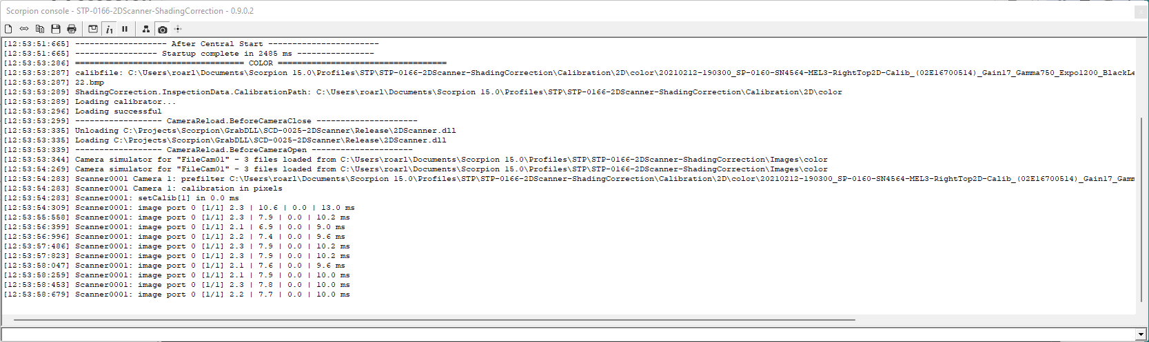
Console window with verbose messages
Note
Setting camera properties via scanner synchronizes properties for all attached cameras and is very useful and faster than accessing each camera.
Any camera property can be accessed with scanners setProperty.
Getting camera properties must be accessed individual, either from actual camera or
cam = GetCamera('Scanner0001')   #get the scanner camera
cam.setProperty('exposure', 1000)  #set continous for all attached cameras
Supported properties
Properties may be accessed by either Scorpion commands or Python camera interface. Cameras attached the scanner may be accessd by prefixing property name by camera<1..b>, i.e “camera1.exposure”
Property |
Access |
Default |
Description |
|---|---|---|---|
scanCount |
R/W |
1 |
configuration value |
calib |
W |
0 |
set index of optional calibration files for all cameras |
minScanCount |
R/W |
0 |
configuration value |
activeGrabTimeout |
R/W |
0 |
configuration value ms |
overlap |
R/W |
0 |
configuration value |
count |
R/W |
current scans in buffer. After completed scan, count is set to 0. By setting count>1 copies the previous scans to top creating an image overlap. |
|
pixelsize |
R |
8 |
mirrored value from camera |
width |
R |
total image width |
|
height |
R |
total image height |
|
passthru |
W |
1 |
set partial image passthru, see PassThru configuration. Set to outside scanCount range to disable passthru. |
scanTime |
R |
total time from first image received until scan complete (ActiveGrabTime) |
|
trigTime |
R |
average trigger period of last scan |
|
activeGrabTimeoutCount |
R |
no of timeouts since initied |
|
cameras |
R |
no of configured cameras |
|
verbose |
R/W |
0 |
print messages to console, 0=None, 1=debug If verbose, for each image received, a console message is generated showing the time consumed by the operations performed
|
camera<n>.<prop> |
Access attached camera property |
Supported commands
Commands may be sent to scanners via Scorpion Python camera interface.
Command |
Parameters |
Description |
|---|---|---|
reset |
fill=value fifo=1 |
reset scan counters. If the optional fill parameter is given, the image buffer is set to value, else kept unchanged. Optional fifo=1 resets the fifo for the scanner’s attached cameras. |
trig |
fill=value |
force trig even if the scan is not complete. Remaining scans are filled with value if specified, else data is kept unchanged |
clear |
fill=value |
clear the image buffer for incomplete scans. If the fill parameter is given, the pixel value is set to value, else 0 |
stat |
prints scanner status to the console |
|
set |
prop=value |
access to any property, including properties supported by setProperty |
get |
prop=name |
returns the property value as a string, including properties supported by getProperty and the following special values camera<n>.resampler.CalibName camera<n>.filter.Args camera<n>.filter.Options inifile - full path of the active 2DScanner.ini imageStatus / status - scanner status as a Python dictionary string meta - completed scan metadata as a JSON string (see metadata) timing - per-camera timing of the completed scan as a JSON string pitch - outgoing pixel size as (x,y) |
save |
<filename> |
save the current configuration to <filename> in the Hardware folder |
load |
<filename> |
load the configuration from <filename> in the Hardware folder and reopen the scanner |
Examples - properties
Example 2a - Set 2DScanner Properties for all cameras
cam = GetCamera('Scanner0001')     #get the scanner camera
cam.setProperty('continous', 1)    #set continous for all attached cameras
cam.setProperty('exposure', 1000)  #set exposure for all attached cameras
Example 2b - Get property enumerated with cameraN
exposure = cam.getProperty('camera1.exposure', 1) #get specific camera
Example 2c - Get property using GetCamera(name)
exposure = GetCamera('0').getProperty('exposure') # equals above
Example 2d - Set 2DScanner Properties
cam = GetCamera('Scanner0001')
cam.setProperty('scanCount', 6)
cam.setProperty('activeGrabTimeout', 6)
Examples - scripts
Example 3a - executeCmd(‘get’,’value=imageStatus’) for Scanner0001 and 0002
def imagestatus():
  cameras = (‘Scanner0001’,’Scanner0002’)

  for cam in cameras:
    print cam,GetCamera(cam).executeCmd('get','value=imageStatus')

# output

[10:41:13:950] Scanner0001 {'imageCount': 2061, 'activeGrabTimeoutCount': 0,'activeGrabTime': 1577, 'trigTime': 65, 'camera0': {'imageCount': 49464, 'activeGrabTimeoutCount': 0}}
[10:41:13:950] Scanner0002 {'imageCount': 2061, 'activeGrabTimeoutCount': 0,'activeGrabTime': 1577, 'trigTime': 65, 'camera0': {'imageCount': 49464, 'activeGrabTimeoutCount': 0}}
Example 3b - executeCmd(‘get’,’value=imageStatus’))
def imagestatus(): # multiple cameras connected to scanner
  print 50*'-'
  status = eval(GetCamera('Scanner0001').executeCmd('get','value=imageStatus')) # imageStatus is returned as a string
  print 'imcnt:',status['imageCount'], 'aGrabTimeoutCnt:',status['activeGrabTimeoutCount'],
  print 'activeGrabTime:',status['activeGrabTime'], 'trigTime:',status['trigTime']
  print 'cam1:',status['camera0']
  print 'cam2:',status['camera1']
  print 'cam3:',status['camera2']

# output

imcnt: 1855 aGrabTimeoutCnt: 0 activeGrabTime: 1891 trigTime: 210
cam1: {'activeGrabTimeoutCount': 2, 'imageCount': 16707}
cam2: {'activeGrabTimeoutCount': 2, 'imageCount': 16707}
cam3: {'activeGrabTimeoutCount': 2, 'imageCount': 16707}
Example 3c - executeCmd(‘stat’)
print GetCamera('Scanner0001').executeCmd('stat') # prints stats to console

# output to console

Scanner0001: last scan 1657 ms, avg trig period 184 ms
Image count 690 timeout count 0
Cam[1] image count 0 total 6218 timeouts 1
Cam[2] image count 0 total 6218 timeouts 1
Cam[3] image count 0 total 6218 timeouts 1
Example 4 - executeCmd(‘reset’,’fill=0’)
cam = GetCamera('Scanner0001')
cam.executeCmd('reset','fill=0')
Example 5 - setProperty(‘verbose’,1) - will output scanner information
The verbose property is good for seeing the details of the image flow
def verbose():
  cam = GetCamera('Scanner0001')
  if cam.getProperty('verbose') == 0:
    cam.setProperty('verbose',1)
  else:
    cam.setProperty('verbose',0)

# sample output

[09:36:55:311] Scanner0001.0 [1/8] 2.7 | 5.1 | 0.0 | 0.2 | 8.0 ms
[09:36:55:311] Scanner0001.1 [1/8] 0.3 | 5.2 | 0.0 | 0.2 | 5.7 ms
[09:36:55:312] Scanner0001.0 [2/8] 0.2 | 4.6 | 0.0 | 0.6 | 5.4 ms
[09:36:55:312] Scanner0001.1 [2/8] 0.2 | 5.1 | 0.0 | 0.2 | 5.5 ms
                           *   *    *     *     *     *     *
                           1   2    3     4     5     6     7

 * 1 - image source (scanner.camera)
 * 2 - partial counters (count/scanCount)
 * 3 - collect time - image collection from camera
 * 4 - resample time
 * 5 - filter time
 * 6 - queue time - gap between collection and start of processing
 * 7 - total processing time