Examples - 2DScanner setup
This chapter contains complete 2DScanner.ini files for the setups that come
up most often, with notes on why each setting is what it is.
Copy the example closest to your system into the profile’s Hardware folder, then change the camera driver name, the ports and the calibration file names.
Note
Start simple. Get one camera scanning in pixel mode first, confirm the image looks right, then add calibration, then add the second camera. Debugging a four camera calibrated stitch from a blank page is much harder than growing into it one step at a time.
Example 10 - the simplest scanner: stack images from one camera
One camera, no calibration, no filter. Every ten grabs are stacked into one tall image. This is the right place to start on any new system.
How it works:
CalibFileis empty, so the scanner runs in pixel mode - the camera image is used as it is and Size / TopLeft are ignored
Scans=10stacks ten camera images on top of each other. If the camera delivers 1024 x 2048, the scanner delivers 10240 x 2048
ActiveGrabTimeout=0means the scanner waits indefinitely for all ten images - nothing is delivered until the scan is complete
Verbose=1prints status messages while you get it working
[Config]
CameraDriver = HVGrab_1_0_4_53.dll
FilterDLL    = SVLImageFilter.dll
ResampleDLL  = SVLResample.dll
ResampleMode = 1
Verbose      = 1

[Scanner0001]
Cameras = 1
Scans   = 10

[Scanner0001.Camera1]
Port      = 0
CalibFile =
Trigger it from a script, one grab per scan line:
cam = GetCamera('Scanner0001')
cam.executeCmd('reset','fill=0')   # start from a clean image
for i in range(10):
  cam.grab()                       # the image arrives after the 10th grab
Example 11 - two cameras side by side, pixel mode
Two cameras widen the field of view. In pixel mode the images are simply placed next to each other - camera 1 on the left, camera 2 on the right - and the result is as wide as both images together.
How it works:
Cameras=2and one[Scanner0001.Camera<n>]section per camera
Portpicks which physical camera feeds which column. Port 0 is the first camera in Scorpion’s camera list
Scans=1means one row - a single wide image per grab, not a scan
ActiveGrabTimeout=300withMinScans=0requires both cameras to deliver within 300 ms of each other. If only one arrives, the pair is discarded - see Example 14 for the reasoningpixel mode tolerates cameras of different size; the shorter image is padded black down to the height of the taller
[Config]
CameraDriver = HVGrab_1_0_4_53.dll
FilterDLL    = SVLImageFilter.dll
ResampleDLL  = SVLResample.dll
ResampleMode = 1
Verbose      = 1

[Scanner0001]
Cameras           = 2
Scans             = 1
ActiveGrabTimeout = 300
MinScans          = 0

[Scanner0001.Camera1]
Port      = 0
CalibFile =

[Scanner0001.Camera2]
Port      = 1
CalibFile =
Example 12 - Scorpion 3D Venom, splitting a mirror image
A Venom camera sees the scene through two mirrors, so one physical image holds two views. This configuration turns each view into its own resampled camera image by running two scanners on the same physical camera port.
How it works:
both scanners use
Port=0- the same raw image feeds botheach scanner has its own calibration file, and each calibration puts its origin (0,0) in the centre of its own mirror
TopLeft_x=-12,TopLeft_y=-10,Size_x=24,Size_y=20describe a 24 x 20 mm area centred on that origin - remember _x is down, _y is across
Pitch_x/Pitch_yof 0.02 mm gives 24/0.02 = 1200 rows by 20/0.02 = 1000 columns out of each scannerin the Scorpion image setup the physical camera is active and the two scanner images are inactive, because the raw image is the one being grabbed
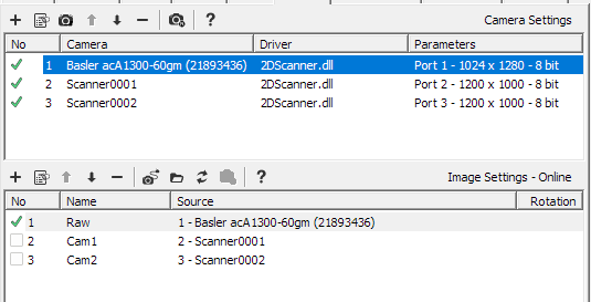
[Config]
CameraDriver = PylonAreaCamera_pylon5_1_5_2_40.dll
FilterDLL    = ScorpionOpenCV.dll
ResampleDLL  = SVLResample.dll
ResampleMode = 1
Verbose      = 0

[Scanner0001]
Cameras   = 1
Scans     = 1
TopLeft_x = -12
TopLeft_y = -10
Size_x    = 24
Size_y    = 20
Pitch_x   = 0.02
Pitch_y   = 0.02
Threaded  = 1

[Scanner0001.Camera1]
Port      = 0
CalibFile = ..\Calibration\2D\CalibrationCam1.ini

[Scanner0002]
Cameras   = 1
Scans     = 1
TopLeft_x = -12
TopLeft_y = -10
Size_x    = 24
Size_y    = 20
Pitch_x   = 0.02
Pitch_y   = 0.02

[Scanner0002.Camera1]
Port      = 0
CalibFile = ..\Calibration\2D\CalibrationCam2.ini
Note
Two cameras within one scanner may also share a port. Use two scanners when the two views should be separate Scorpion images, and one scanner with two cameras when they should be stitched into a single wider image.
Example 13 - two cameras scanning a conveyor
Two cameras over a conveyor, each building a long image from 50 narrow strips. This is the classic linescan replacement.
How it works:
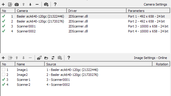
Scans=50- fifty triggers make one image. WithSize_x=100andPitch_x=0.5each strip is 200 rows tall, so the finished image is 10000 rows tall
Size_y=329atPitch_y=0.5gives 658 columns acrosseach camera has three calibration files for three working heights - the parent section is calibration 0,
.Calib1and.Calib2are 25 mm and 50 mm. Switch withsetProperty('calib', n)
Threaded=0turns off threaded resampling. For strips this narrow the thread costs more than it saves - worth testing both ways on your systemin the Scorpion image setup the scanner images are active and the physical camera images inactive
[Config]
CameraDriver = PylonAreaCamera_pylon5_1_5_2_40.dll
FilterDLL    =
ResampleDLL  = SVLResample.dll
ResampleMode = 1
Verbose      = 0

[Scanner0001]
Cameras           = 1
Scans             = 50
Overlap           = 0
ActiveGrabTimeout = 0
MinScans          = 0
TopLeft_x         = 100
TopLeft_y         = 0
Size_x            = 100
Size_y            = 329
Pitch_x           = 0.5
Pitch_y           = 0.5
Threaded          = 0

[Scanner0001.Camera1]
Port      = 0
CalibFile = ..\Calibration\2D\ExtRefCam1_0mm.ini

[Scanner0001.Camera1.Calib1]
CalibFile = ..\Calibration\2D\ExtRefCam1_25mm.ini

[Scanner0001.Camera1.Calib2]
CalibFile = ..\Calibration\2D\ExtRefCam1_50mm.ini

[Scanner0002]
Cameras   = 1
Scans     = 50
TopLeft_x = 100
TopLeft_y = 0
Size_x    = 100
Size_y    = 329
Pitch_x   = 0.5
Pitch_y   = 0.5
Threaded  = 0

[Scanner0002.Camera1]
Port      = 1
CalibFile = ..\Calibration\2D\ExtRefCam2_0mm.ini

[Scanner0002.Camera1.Calib1]
CalibFile = ..\Calibration\2D\ExtRefCam2_25mm.ini

[Scanner0002.Camera1.Calib2]
CalibFile = ..\Calibration\2D\ExtRefCam2_50mm.ini
Switching working height at run time:
for scanner in ('Scanner0001','Scanner0002'):
  GetCamera(scanner).setProperty('calib', 1)   # 25 mm
Note
Overlap is worth adding when individual objects are scanned on a moving
conveyor. Overlap=5 copies the last five strips of each image to the top of
the next one, so an object crossing the image boundary appears whole in at
least one of them.
Example 14 - stereo vision, two images captured together
Here the 2DScanner is not used to build a long image at all - it is used to guarantee that two stereo images belong to the same moment.
How it works:
Scans=1- one row, so the finished image is just the two views side by side
ActiveGrabTimeout=300- the second image must arrive within 300 ms of the first, in either order
MinScans=0- if it does not, the pair is discarded silently. The inspection never sees a mismatched stereo paireach camera is calibrated with its origin at the image centre and a 440 x 600 area, giving a 440 x 1200 pixel result at
Pitch=1
[Config]
CameraDriver = HVGrab_1_0_4_53.dll
FilterDLL    = SVLImageFilter.dll
ResampleDLL  = SVLResample.dll
ResampleMode = 1
Verbose      = 0

[Scanner0001]
Cameras           = 2
Scans             = 1
Overlap           = 0
ActiveGrabTimeout = 300
MinScans          = 0
Pitch_x           = 1
Pitch_y           = 1
Threaded          = 1

[Scanner0001.Camera1]
Port      = 0
TopLeft_x = -220
TopLeft_y = -300
Size_x    = 440
Size_y    = 600
CalibFile = ..\Calibration\2D\CalibrationCam1.txt

[Scanner0001.Camera2]
Port      = 1
TopLeft_x = -220
TopLeft_y = -300
Size_x    = 440
Size_y    = 600
CalibFile = ..\Calibration\2D\CalibrationCam2.txt
Note
Why MinScans matters here. When a network delay holds the second image back, the timeout fires on the first image alone. The delayed image then arrives on its own and causes a second, false timeout while it waits for a partner that will never come.
With MinScans=0 both are discarded and the inspection simply misses that
cycle - which is what you want for stereo.
With MinScans=1 the scanner delivers two images instead, each with the
missing half filled black. Use it only if your inspection can recognise and
reject a half-black image.
Example 15 - shading correction at two working heights
One camera with flat-field shading correction, configured for two heights. Because the illumination profile changes with height, each calibration gets its own correction image.
How it works:
ImageFilterType = fselects the flat-field filter
ImageFilterArgsis the shading correction image, captured on a uniform white target with the same lens, lighting, gain and exposure as production
ImageFilterOptions = -t92sets the white-point target to 92 counts. Without-tthe brightest pixel in the correction image is used instead, which makes the result depend on a single pixelthe parent camera section is calibration 0 and
.Calib1is calibration 1. Both repeat the filter keys, because filter settings do not inherit into aCalibsub-section
CalibFileis empty here - shading correction works fine in pixel mode
[Config]
CameraDriver = PylonAreaCamera2_pylon5_1_5_3_52.dll
FilterDLL    = SVLImageFilter.dll
ResampleDLL  = SVLResample.dll
ResampleMode = 1
Verbose      = 1

[Scanner0001]
Cameras           = 1
Scans             = 1
Overlap           = 0
ActiveGrabTimeout = 0
MinScans          = 0
Threaded          = 1

[Scanner0001.Camera1]
Port               = 0
ImageFilterType    = f
ImageFilterArgs    = ..\Calibration\2D\color\Calib_0mm_Gain17_Expo1200.bmp
ImageFilterOptions = -t92
CalibFile          =

[Scanner0001.Camera1.Calib1]
ImageFilterType    = f
ImageFilterArgs    = ..\Calibration\2D\color\Calib_50mm_Gain17_Expo1200.bmp
ImageFilterOptions = -t92
CalibFile          =
Switching between the two at run time:
cam = GetCamera('Scanner0001')
cam.setProperty('calib', 0)    # 0 mm correction image
cam.setProperty('calib', 1)    # 50 mm correction image
Checking that the correction image was actually loaded:
print cam.executeCmd('get','camera1.filter.calibstatus')   # ok / missing / error text
print cam.executeCmd('get','camera1.filter.calibmax')      # brightest pixel found
Note
calib switches every camera in the scanner at the same time, so all
cameras must have the same number of Calib sections.
Example 16 - two resampled areas from one camera
Two cameras in a scanner may share a physical port. Each gets its own calibration and its own area of the raw image, and the two resampled areas are stitched side by side into one image. This is a neat way to cover a wide object with fewer cameras when the optics allow it.
How it works:
cameras 1 and 2 both use
Port=0, cameras 3 and 4 both usePort=1- two physical cameras produce four columnseach of the four has its own calibration file, so its
TopLeft_yandSize_yare relative to that calibration’s origin. They are all negative here simply because each calibration puts its origin near the middle of the area it covers - they are not positions on a shared axis
TopLeft_x,Size_xand bothPitchvalues come from the scanner section, since all four areas share the same vertical extent and resolutionwith
Pitch_y=0.6, camera 1 contributes 860/0.6 = 1433 columns and camera 2 contributes 800/0.6 = 1333; the finished image is as wide as all four together
Scans=6stacks six of these four-wide rows into the finished image
[Config]
CameraDriver = HVGrab_1_0_4_53.dll
FilterDLL    = SVLImageFilter.dll
ResampleDLL  = SVLResample.dll
ResampleMode = 1
Verbose      = 1

[Scanner0001]
Cameras   = 4
Scans     = 6
TopLeft_x = -18
Size_x    = 36
Pitch_x   = 0.6
Pitch_y   = 0.6

[Scanner0001.Camera1]
Port      = 0
TopLeft_y = -460
Size_y    = 860
CalibFile = ..\Calibration\2D\CenterCam1-1.txt

[Scanner0001.Camera2]
Port      = 0
TopLeft_y = -400
Size_y    = 800
CalibFile = ..\Calibration\2D\CenterCam1-2.txt

[Scanner0001.Camera3]
Port      = 1
TopLeft_y = -400
Size_y    = 800
CalibFile = ..\Calibration\2D\CenterCam2-1.txt

[Scanner0001.Camera4]
Port      = 1
TopLeft_y = -400
Size_y    = 860
CalibFile = ..\Calibration\2D\CenterCam2-2.txt
Note
Always set TopLeft_y and Size_y explicitly in every camera section when
several calibrated cameras are stitched. The scanner does derive a default
position for the next camera, but making it explicit is the only way to keep
the layout obvious and predictable.
Which column a camera ends up in is decided by the order of the camera
sections, not by the coordinates - Camera1 is always leftmost.
Example 17 - high frame rate scanning
Settings for two cameras running at around 50 fps, where the cameras must not be allowed to fall behind while a finished scan is handed to Scorpion. Requires version 1.1.0.32 or later.
How it works:
RingSize=64doubles the capture buffer. The default of 32 covers roughly 0.6 s at 50 fps; raise it if the log reports frame loss during bursts
WorkerRtPriority=8runs the capture threads at real-time priority so they are not held up by other work on the machine
Threaded=1keeps resampling off the capture thread
PassThruis left empty - no raw images are passed alongside the stitched one, so nothing competes with the cameras for time
ResampleMode=1- nearest neighbour is the fastest resampler. Use 0 for bilinear if image quality matters more than rate
Verbose=2gives one diagnostic line per finished scan with the per-camera frame rate and its stability, without the per-image cost of level 3
[Config]
CameraDriver = HVGrab_1_0_4_53.dll
FilterDLL    = SVLImageFilter.dll
ResampleDLL  = SVLResample.dll
ResampleMode = 1
Verbose      = 2

[Scanner0001]
Cameras          = 2
Scans            = 100
Threaded         = 1
RingSize         = 64
WorkerRtPriority = 8
PassThru         =

[Scanner0001.Camera1]
Port      = 0
CalibFile =

[Scanner0001.Camera2]
Port      = 1
CalibFile =
Confirming the cameras keep up:
cam = GetCamera('Scanner0001')
print cam.executeCmd('get','meta')     # framerate and std per camera
print cam.executeCmd('get','timing')   # collect | resample | filter | queue
Read the numbers like this:
framerate should match the camera setting; std should stay small. A rising std means the cameras are not being serviced evenly
a large queue time means processing cannot keep up - lower the rate, switch off filtering, or use nearest neighbour resampling
lostpacket counting up points at network bandwidth, not at the scanner
Note
On SMARTedge, real-time priority needs the real-time privilege. Without it the driver logs a warning and carries on at normal priority - scanning still works, but timing is less even.
Example 18 - continuous scanning
Note
SMARTedge only. On Windows, continuous is forwarded to the attached
cameras instead of driving the scanner - see the warning in Continuous
scanning in the user guide.
From version 1.1.0.32 the scanner can drive itself on SMARTedge, with no trigger script and no external signal. It is the fastest way to get a live image while aiming cameras and setting exposure.
Two timing modes:
delay - wait this many ms after each finished scan, then start the next. The rate follows whatever the system can manage
period - start a scan every this many ms, measured from the previous scan start. Use it when the rate must be constant
cam = GetCamera('Scanner0001')

cam.executeCmd('continuous','start delay=100')    # 100 ms between scans
cam.executeCmd('continuous','start period=500')   # a scan every 500 ms
cam.executeCmd('continuous','stop')

print cam.executeCmd('continuous','status')
# {'continuous': 1, 'delay': 100, 'period': 0}
The same thing with properties, which is convenient from a DataInput page:
cam.setProperty('continuousDelay', 100)   # preset the timing
cam.setProperty('continuous', 1)          # start
cam.setProperty('continuous', 0)          # stop
Note
period wins over delay - set continuousPeriod to 0 to use delay mode.
Continuous mode keeps going until it is stopped or the scanner is closed. Remember to stop it before switching calibration or reloading a configuration.
Example 19 - a real five camera SMARTedge scanner
This is the working configuration of a Pepsico arc detection scanner (SP0177-08, hardware SN8235). Five colour cameras look down at a conveyor and are stitched into one image just over a metre wide. It is a good example to study because everything is calibrated, everything is shading corrected, and every number in the file has a reason.
The system at a glance:
5 x MV-CU013-A0GC colour GigE cameras, 1280 x 1024 sensor, cropped to a 1280 x 500 band
each camera 3D calibrated by a separate Scorpion alignment profile
each camera flat-field corrected with its own shading image
running on SMARTedge (Linux ARM64), so the plugins are
.sofilesresult: one 5250 x 450 pixel image covering 1050 x 90 mm at 0.2 mm per pixel
[Config]
#CameraDriver=libsamplegrab.so
CameraDriver=libhvgrab.so
FilterDLL=libsvlimagefilter.so
ResampleDLL=libsvlresample.so
ResampleMode=1
Verbose=3

[Scanner0001]
Cameras=5
Scans=1
Overlap=0
ActiveGrabTimeout=0
ImageDelay=0
MinScans=0
Scale_x=1
Scale_y=1
TopLeft_x=0
TopLeft_y=0
Size_x=90
Size_y=1050
Pitch_x=0.2
Pitch_y=0.2
PassThru=
Active=0
DiscardLostPacket=0
DiscardSeqError=0
DiscardSyncError=0
Threaded=1
WorkerRtPriority=8
RingSize=32

[Scanner0001.Camera1]
Port=0
TopLeft_x=-45
TopLeft_y=-105
CalibFile=../calibration/2D/SP0177-07-SN8235-Pepsico Arc Detection Scanner Alignment_Cam1_20260429_085449_Bin1x1_Offs245x0_ROI500x1280_UpLeft45x105.txt
ImageFilterType=f
ImageFilterArgs=../calibration/2D/SP0177-07-SN8235-Pepsico Arc Detection Scanner Alignment_shade_Cam1_ScanCam1_20260428_171658_size450x1050.bmp
ImageFilterOptions=-t192-g1.0-o0-fbgr

[Scanner0001.Camera2]
Port=1
TopLeft_x=-45
TopLeft_y=-105
CalibFile=../calibration/2D/SP0177-07-SN8235-Pepsico Arc Detection Scanner Alignment_Cam2_20260430_130832_Bin1x1_Offs245x0_ROI500x1280_UpLeft45x105.txt
ImageFilterType=f
ImageFilterArgs=../calibration/2D/SP0177-07-SN8235-Pepsico Arc Detection Scanner Alignment_shade_Cam2_ScanCam2_20260428_171711_size450x1050.bmp
ImageFilterOptions=-t192-g1.0-o0-fbgr

[Scanner0001.Camera3]
Port=2
TopLeft_x=-45
TopLeft_y=-105
CalibFile=../calibration/2D/SP0177-07-SN8235-Pepsico Arc Detection Scanner Alignment_Cam3_20260429_090000_Bin1x1_Offs245x0_ROI500x1280_UpLeft45x105.txt
ImageFilterType=f
ImageFilterArgs=../calibration/2D/SP0177-07-SN8235-Pepsico Arc Detection Scanner Alignment_shade_Cam3_ScanCam3_20260430_122116_size450x1050.bmp
ImageFilterOptions=-t192-g1.0-o0-fbgr

[Scanner0001.Camera4]
Port=3
TopLeft_x=-45
TopLeft_y=-105
CalibFile=../calibration/2D/SP0177-07-SN8235-Pepsico Arc Detection Scanner Alignment_Cam4_20260429_090130_Bin1x1_Offs245x0_ROI500x1280_UpLeft45x105.txt
ImageFilterType=f
ImageFilterArgs=../calibration/2D/SP0177-07-SN8235-Pepsico Arc Detection Scanner Alignment_shade_Cam4_ScanCam4_20260428_171727_size450x1050.bmp
ImageFilterOptions=-t192-g1.0-o0-fbgr

[Scanner0001.Camera5]
Port=4
TopLeft_x=-45
TopLeft_y=-105
CalibFile=../calibration/2D/SP0177-07-SN8235-Pepsico Arc Detection Scanner Alignment_Cam5_20260429_090315_Bin1x1_Offs245x0_ROI500x1280_UpLeft45x105.txt
ImageFilterType=f
ImageFilterArgs=../calibration/2D/SP0177-07-SN8235-Pepsico Arc Detection Scanner Alignment_shade_Cam5_ScanCam5_20260428_171735_size450x1050.bmp
ImageFilterOptions=-t192-g1.0-o0-fbgr
Working out the geometry
The scanner section describes the whole stitched area in millimetres, and the driver divides it between the cameras. Remember that _x is down the image and _y is across it.
Step |
Value |
Where it comes from |
|---|---|---|
Total area |
90 x 1050 mm |
|
Cameras |
5 |
|
Area per camera |
90 x 210 mm |
|
Resolution |
0.2 mm per pixel |
|
Output per camera |
450 x 1050 pixels |
90/0.2 rows by 210/0.2 columns |
Stitched image |
5250 x 450 pixels |
5 cameras across, |
Warning
Do not confuse the two 1050s. Size_y=1050 is millimetres across the whole
scanner; the 1050 in the output is pixels from one camera. They happen to
be equal here because 1050 mm / 5 cameras / 0.2 mm = 1050 pixels. Change the
pitch and they part company immediately.
Each camera section sets TopLeft_x=-45 and TopLeft_y=-105 - half of
90 and half of 210. That places the resampled area exactly centred on that
camera’s own calibration origin:
centre x = -45 + 90/2 = 0
centre y = -105 + 210/2 = 0
All five cameras use the same numbers, which surprises people the first time they see it. It works because each camera has its own calibration file with its own origin - the coordinates are relative to that camera, not to a shared axis running across the machine.
Note
Position in the stitched image comes from the order of the sections, not
from the coordinates. Camera1 is leftmost, Camera5 rightmost, whatever
their TopLeft_y says. To reorder the strips, change the Port numbers.
Note also that the camera sections do not set Size_x or Size_y - they
inherit 90 and the automatic 1050/5 split from the scanner section. Only
TopLeft is set per camera. This keeps the file short and means the whole
field of view can be re-scaled from two numbers.
The calibration files
Each camera has its own calibration, produced by a separate Scorpion alignment
profile - SP0177-07-SN8235-Pepsico Arc Detection Scanner Alignment - using
the same cameras, lenses and mounting as the running system. That profile is
kept alongside the production profile and re-run whenever the mechanics are
disturbed.
Opening one of the files shows what it holds:
[system]
Profile=SP0177-07-SN8235-Pepsico Arc Detection Scanner Alignment
Tool=Align_Cam1.3DResampleRef
[calib]
model=3
order=9
unit=mm
polynomial=...
revpolynomial=...

* ``Tool=Align_Cam1.3DResampleRef`` - the calibration came from a **3D**
  resample reference tool. This is what makes five cameras line up at the
  seams; with 2D calibration only, the strips would not meet cleanly
* ``unit=mm`` - the object coordinates in ``2DScanner.ini`` are millimetres
* ``model=3``, ``order=9`` - a 9th order polynomial lens model, forward and
  reverse, which is what removes the distortion
The file name is worth reading too, because it records the camera setup that was in force when the calibration was made:
Name fragment |
Meaning |
|---|---|
|
which camera |
|
the date it was made - check this after any mechanical work |
|
no binning |
|
sensor offset, 245 rows down, 0 across |
|
the camera ROI, 500 rows by 1280 columns |
|
the |
Warning
A calibration is only valid for the camera setup it was made with. If binning, ROI or sensor offset change, the calibration is wrong and must be redone. Encoding them in the file name, as here, makes a mismatch easy to spot during service - compare the name against the camera settings file.
Because these cameras are cropped in the sensor rather than in software, the
crop is part of the camera setup and CropOffset / CropSize are not
needed in 2DScanner.ini.
The shading correction
Every camera runs the flat-field filter, ImageFilterType=f, against its own
correction image. The important detail is the size.
The images on disk are 1050 x 450 pixels - and the file name says
size450x1050, rows first, following the same x is down convention as the
ini. That is exactly the resampled output size worked out above, not the
1280 x 500 raw camera image.
Warning
On a calibrated camera the shading image must match the resampled output, not the camera. The filter runs after the resampler, on the image the resampler produced.
In pixel mode there is no resampler, so the shading image must match the camera image instead.
Get this wrong and the filter reports a size mismatch and stays inactive - the images keep coming, just uncorrected. Check it with:
print GetCamera('Scanner0001').executeCmd('get','camera1.filter.calibstatus')
Now the options, -t192-g1.0-o0-fbgr. They are run together without spaces,
which is equivalent to -t192 -g1.0 -o0 -fbgr:
Option |
Effect here |
|---|---|
|
white-point target 192. The correction is normalised so 192 counts means “leave this pixel alone”. Deliberately below 255, which keeps headroom so corrected bright areas do not clip |
|
no brightness change - the filter only evens the image out |
|
no black-level shift |
|
load the correction image as 3-channel BGR colour |
Note
Why -fbgr and not a Bayer pattern. These are Bayer sensors, but
smartedge.conf has RawBayer = 0, so the camera driver demosaics before
the 2DScanner ever sees the image. From the filter’s point of view the input is
ordinary BGR colour, so the correction image is loaded as BGR.
Set RawBayer = 1 and the driver would deliver raw Bayer instead, and -f
would have to name the sensor pattern - gr, rg, gb or bg.
Note
A target of 0 would tell the filter to use the brightest pixel it finds in
the correction image, which makes the whole result depend on one pixel - and on
any dust or specular highlight that happened to be there. Setting -t
explicitly, as here, is the more repeatable choice.
Running it on SMARTedge
A few things in this file are there because it runs on SMARTedge rather than Windows:
the plugins are named as Linux shared objects -
libhvgrab.so,libsvlimagefilter.so,libsvlresample.so. The same file would work on Windows with the.dllnames, and the driver translates in that direction automaticallypaths use forward slashes and are relative to the folder holding
2DScanner.ini
WorkerRtPriority=8needs the real-time privilege on the device. Without it the driver logs a warning and carries on at normal priority - scanning still works, it is just less even
PassThru=is empty, and on SMARTedge pass-through is ignored in any case
#CameraDriver=libsamplegrab.soon the first line is the simulation driver, commented out. Swap the comment over and the scanner replays stored images instead of talking to hardware, which is how the configuration is tested off the machine
The cameras themselves are configured outside this file, in the hardware
folder next to it - one .mfs settings file per camera, named after its
serial number. That is where exposure, gain, ROI and trigger mode live.
Note
Verbose=3 prints a timing line for every image - five lines per scan
here. That is right while commissioning, but it costs time on a running system.
Drop it to 1, or to 2 if you want the per-scan frame rate summary:
GetCamera('Scanner0001').setProperty('verbose', 1)
Both ; and # start a comment line on SMARTedge. Only ; is a real
comment on Windows, so prefer ; in files that move between the two.
Commissioning checks
With a scanner this size it pays to confirm each stage separately:
cam = GetCamera('Scanner0001')

# 1. did every camera get its calibration and its shading image?
for i in range(1,6):
  print i, cam.executeCmd('get','camera%d.resampler.calibfile' % i)
  print i, cam.executeCmd('get','camera%d.filter.calibstatus' % i)

# 2. is the stitched image the size we expect - 5250 x 450?
print cam.getProperty('width'), cam.getProperty('height')

# 3. are the five cameras running at the same rate and staying in step?
print cam.executeCmd('get','meta')

# 4. where is the time going?
print cam.executeCmd('get','timing')

* ``calibstatus`` must be ``ok``. ``missing`` means the file was not found;
  anything else is the reason it could not be read
* ``width`` x ``height`` confirms the geometry maths above. A wrong width
  usually means a camera failed to open and was left out
* in ``meta``, the five ``framerate`` values should agree and ``std`` should be
  small. ``lostpacket`` counting up points at network bandwidth
* to see one camera on its own while aiming or focusing, bypass its filter
  temporarily with ``cam.setProperty('camera3.filter.active', 0)``